Hello! This blog post is intended as the first part of a series about Wi-Fi. In this first post, however, there will be little about Wi-Fi itself (Wi-Fi as a communication protocol, topics that will be developed over the course of the posts). I wanted to start this series by describing the basics of wireless communication: what needs to happen for digital information to travel wirelessly to another device.
I will try to keep all explanations as simple as possible. This means that I will be taking some licenses in the development of these explanations, but I’m doing it for two reasons: the length of the post, and the amount of maths needed. What I am looking for with this first post is to introduce concepts that are common to all wireless communication. Because these concepts will later be necessary to understand some of the whys and wherefores of Wi-Fi.
Who is this series aimed for? Anyone who wants to understand a little better how their Wi-Fi network works, or wants to start discovering the dark world of wireless communications.
What is wireless communication?
Let’s start with the basics: what is wireless communication?
First of all, it is a communication, so it involves two or more devices. As in any communication, there will be data transmitting devices (Tx) and data receiving devices (Rx). The word wireless refers to the channel through which this communication takes place. Instead of using wires (copper or optical), a wireless communication takes place over electromagnetic fields. Data travels within electromagnetic waves.
One of the most significant aspects of these communications is that the channel is always shared. And not just shared between the devices relevant to our communication, but any device that can communicate wirelessly. Knowing this is key to make these systems work and to keep communications secure. In each country there are regulations that apply to the use of the electromagnetic spectrum, but then each communication protocol will establish its own mechanisms to avoid interference and to secure the data that is being sent.
To really understand how this type of communication works, we need to know the channel very well. Let’s now focus on some key points of this wireless channel:
- What is an electromagnetic wave? How can it be described?
- How do I generate waves? How do I listen to the generated waves?
- How is information introduced into these waves?
- How do two wireless communication systems coexist ‘seamlessly’?
Waves: What are they?
Basic definition
A wave is a physical term. It describes energy propagating through space that disturbs some parameter of this space in its path. First point: the wave is just energy, it has no matter.
What then can a disturbance be? An example known to all is sound. Sound is a wave that travels by modifying the air pressure. Our ears react to this modification of the pressure in the air around us, and so we hear (thanks to the brain, too).
More details about sound in the YouTube video below (optional):
Note: Sound modifies the air through which it travels. Therefore, it needs air to travel (or another medium, but it needs matter), and so it is not transmitted in a vacuum.
Since there are different disturbances (which characteristic is disturbed and which medium is disturbed), there are different types of waves. In the case of sound again, waves are of the mechanical type. This is because the property that is changed (pressure) is a mechanical property.
Going back to wireless communications, the type of wave that governs this world are the so-called electromagnetic waves. Electromagnetic waves disturb electromagnetic fields, causing them to oscillate as they travel through space. The air through which sound travels is probably known to everyone, but electromagnetic fields are not. And it is one of the most complex explanations to make.
Electromagnetic fields
Getting to know at least the basics of an electromagnetic field is essential to understanding some aspects of wireless communications. An electromagnetic field is our medium over which the communication is established.
An electromagnetic field has two parts: an electric and a magnetic part. For an electric field to propagate, both parts must always exist. Electricity and magnetism are two sides of the same coin, and once these fields are generated, they will travel at the speed of light as long as the conditions for both exist.
To generate these fields, everything starts by moving electric charges (i.e. alternating current on a conductor such as copper). This movement of charges generates an electric field and a magnetic field, which propagate by feeding back on each other.
Characteristics of a wave
Waves of any kind share certain common characteristics which are used to describe them and work with them.
Firstly, given the nature of the disturbances many of them generate, they are usually described with trigonometric functions (or a set of them) resulting in images such as the one shown in Figure 1 to represent them. The wave drawn has a sine wave shape, repeating its pattern in time.
There is another characteristic that must always be taken into account to understand the behaviour of waves, especially in the field of telecommunications: waves vary in time and, in addition, they travel through space. In both cases, they do so with sine shapes. Returning to Figure 1, we can see that it shows the wave at different points in space (the horizontal axis describes the distance). But remember that each point of that wave (‘y’, for example) will vary in time in a sine-wave fashion. The animation in Figure 2 shows this behaviour.
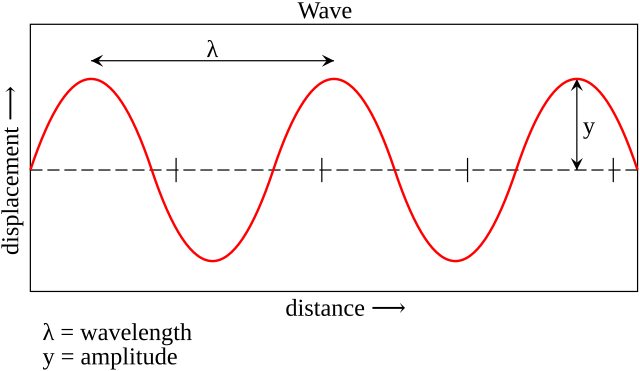

There are four fundamental properties to describe a wave, which are explained below. These terms will be used very frequently later on, when understanding how to send information over these waves.
- Frequency: The frequency of a wave is defined as the number of oscillations it makes in one second. This means how many times it repeats its pattern within this period of time.
- Amplitude: This is the maximum intensity of the wave. This maximum value can vary at each point in space, for reasons that will be explained later.
- Wavelength (λ): A wave repeats its pattern and also moves in space. It happens then that, at the same instant, two points in space are at the same value (see Figure 2, the two points marked in red). The minimum distance between these points is known as the wavelength. Its relationship to frequency is inversely proportional (lower frequency means longer wavelength).
- Phase: A property that compares two waves. Suppose two waves oscillate in time in the same way but with a certain displacement (in time and, consequently, also in space). Phase is the way to measure this displacement.
Antennas
So far, we have seen that we need electromagnetic for wireless communications. In this section, we will explain how these waves are generated and how we can make them travel through space.
The generation part is less relevant: is made by electrical circuits. These circuits oscillate electrical signals at the desired frequency. So we have the electric field needed for the electromagnetic wave, which in turn will generate the magnetic field. The question is, how do we get that signal out of the electrical circuit and into space? The answer is a key element: an antenna.
An antenna introduces a discontinuity in the electrical circuit. In its most basic form, a conductor with an open end. If the length of this conductor is proportional to the wavelength of the electrical signal, this signal will reflect in the conductor in such a way that it ends up radiating power in the form of an electromagnetic wave.
From this basic principle, different antenna designs with different characteristics appear. But before describing these characteristics, it is important to emphasise one point from the previous explanation: the antenna is designed for a specific frequency (in practice, a limited range of frequencies), and it will deliver the capabilities described by the manufacturer only at this frequency.
In the communications field, we are interested in another property of an antenna: its reciprocity. This, described at a high level, implies that an antenna does the reverse work with the same characteristics. It can transform waves into electrical signals. Therefore, the same antenna can both transmit and receive waves with the same properties.
Antenna characteristics
The first properties of an antenna that we will notice are those related to its signal conversion work. Here, the operating frequency and impedance matter. It is important to respect both properties when selecting an antenna for a specific transmitter or receiver circuit.
Another fundamental property of an antenna, and one that is relevant when designing a wireless link is its gain. As we have seen, an antenna radiates waves into space. But in which direction does it do so?
To represent the way an antenna radiates we use radiation patterns. There are two types: three-dimensional and polar planes. The three-dimensional pattern is used to get an idea of what the radiation pattern looks like. The polar planes represent two cuts to the three-dimensional pattern: one on the horizontal plane (azimuth) and one on the vertical plane (elevation).
An antenna that radiates the same power in all directions is known as an isotropic antenna. Although this antenna is only theoretical, it is used as the gain reference for other antennas. An isotropic antenna has a gain of 0 dB in all directions. The gain of other antenna types is then calculated as the difference with respect to the isotropic antenna. This unit of measurement is known as dBi.
The power it emits is homogeneous in all directions. Let’s look at the radiation patterns of this type of antenna.
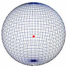
Figure 3: Three-dimensional radiation pattern of an isotropic antenna.
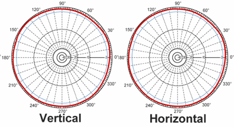
Figure 4: Polar planes radiation pattern of an isotropic antenna.
Most of the information can be found in the patterns shown in Figure 4:
- The antenna would be located at the centre of each plane.
- The polar pattern shows the gain of the antenna in each direction (radiation angle).
- The gain is drawn with a red line. The further away from the centre, the higher the gain.
- In the case of the isotropic antenna, as explained above the gain remains the same in all directions. So, for all angles the distance to the centre will be the same. That is why the shape of the radiation pattern is a circle.
- Many polar diagrams are normalised. This means that they take the point of highest gain as a reference and apply the scale on this point. This point will be better reflected in the other antenna types we will discuss.
We should remember that the isotropic antenna is ideal, it does not exist in reality. Therefore, let’s look at commercial antenna types below.
Omnidirectional antenna
The omnidirectional antenna is the most similar to the isotropic antenna that we can find commercially. Let’s start by looking at the radiation patterns and then analyse their characteristics and uses.
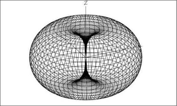
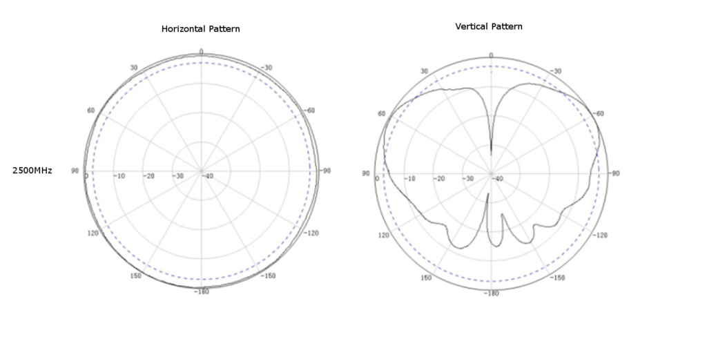
This type of antenna is symmetrical in its horizontal plane, same as the isotropic antenna. This is evident from the fact that the gain remains constant in this plane. However, we do see changes in the vertical plane.
The most important change is the abrupt drop in gain at 0 and 180 degrees (that would be exactly above and below the antenna). These are known as nulls, and are present in all antennas.
Omni-directional antennas are typically used when we want to reach multiple devices that may be scattered around the antenna in all directions. In a Wi-Fi network for example, this type of antennas is used in access points that are installed in offices or in a home access point.
Directional antenna
Omnidirectional antennas radiate their power equally in all directions in their horizontal plane. If we need to concentrate the power in a single direction, directional antennas must be used. This type of antenna is built in such a way to obtain radiation patterns like the one shown in the following figures.
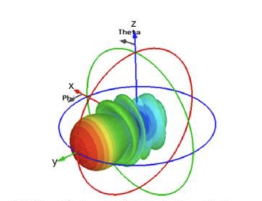
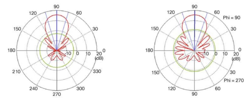
We can see that in this case the power is concentrated in a specific direction. Outside that direction the power drops abruptly, we see first nulls. The area of highest power concentration between these first nulls is called the main lobe, or main beam. However, the antenna is not perfect and other smaller ‘peaks’ of power appear. These are called side lobes, and are generally unwanted (we try to reduce them as much as possible).
We can make a sub-categorisation of directional antennas according to the width of their main lobe. The width is measured in degrees, and we use as cut-off the point at which the gain drops 3 dB (i.e. is halved from the maximum gain). Common examples are antennas with 30° width, or others with 120° width. Which one to use depends on the use case.
Directional antennas with very narrow main lobes are mainly used in point-to-point radio links. By concentrating all the energy in a specific direction, we can reach longer communication distances (we will see why when we analyse propagation).
On the other hand, we could create 120º sectors (one antenna per sector) and cover a total of 360° . Each antenna is responsible for serving the users in its sector. This is a common deployment in cellular technology.
Propagation
Let’s leave antennas aside for the moment, and move on to another very important topic. So far we learned how a wave that will be used to carry information looks like, and how we generate these waves and send them out into space. But what happens once the wave leaves the antenna? A wave will travel in all directions, with a power proportional to the gain of that antenna. This is called wave propagation.
As the waves propagate through space, they travel away from the transmitting device. Our goal in the world of communications is make these waves reach the antenna of the receiving device. But it makes sense to think that the transmitter and receiver can only be a certain distance apart for communication to take place. The aim of this section is to understand why this happens.
We saw in the previous sections that a transmitter generates waves with a certain power. This power will be concentrated in certain directions by the antenna connected to the transmitter. But the wave will travel in all directions, with more or less power depending on the gain of the antenna in that direction. This means that, if we stand at a certain distance from the transmitter, the total power must be distributed in a spherical area that includes all points at that distance from the transmitter.
Now let’s place ourselves at a further distance from the transmitter. Again, the total power must be distributed to all points at this distance from the transmitter. The total area of the new sphere is larger than the previous area. Or to put it another way, at a specific point we will have less power the further we move away from the transmitter. Let’s look at a picture to help understanding:
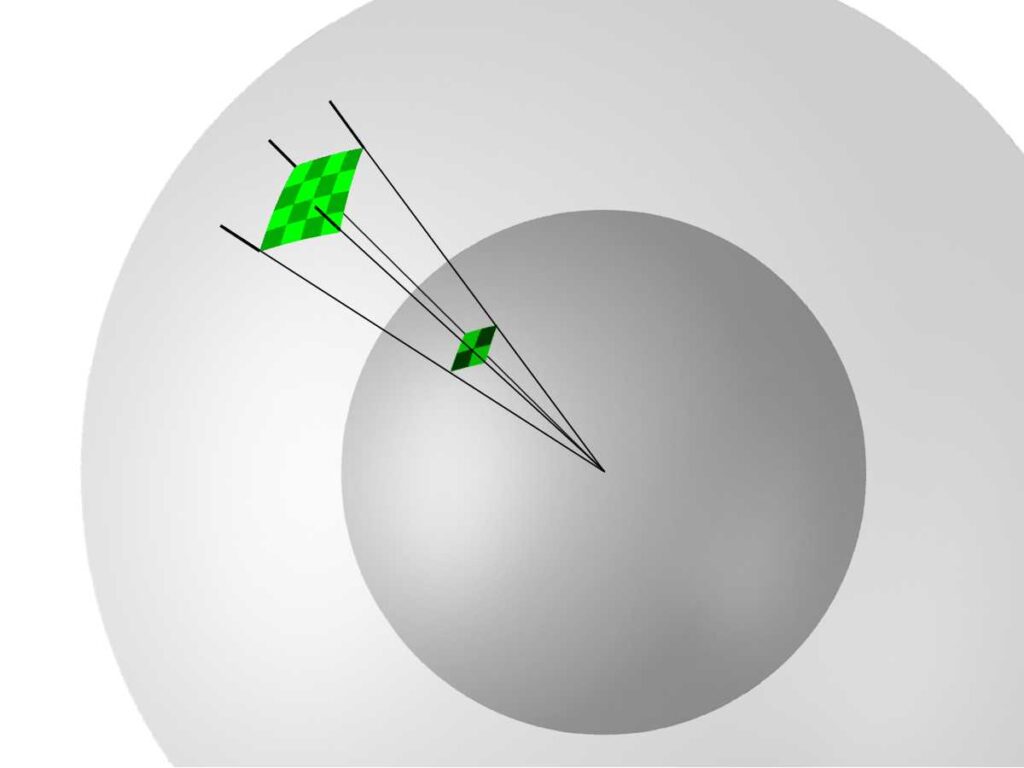
In communications this is considered as a loss of power as we move away from the transmitter. Specifically, it is called Free-Space Path Loss, or Free-Space Loss.
These losses have a specific formula. The details are not relevant for the purpose of this post, but it is important to know that the power of our wave will decrease proportionally to the square of the distance that separates it from the transmitter. This makes it a very considerable loss, and without taking into account other sources of losses that exist in a real transmission.
There is another factor that affects free space losses: the frequency of the wave. The losses increase with the square of the frequency. This means that the higher the frequency, the greater the free space losses.
Received power calculation
To conclude these fundamental concepts of electromagnetic waves transmission we must know how the power of the wave is calculated when it reaches the receiver. The factors that we take into account are:
- Transmitted power – base power of the wave.
- Transmitting antenna gain in the direction towards the receiver – as it concentrates power (or not) in this direction.
- Free space loss – proportional to the distance separating transmitter and receiver and the frequency of the wave.
- Other propagation losses – we will not go into details but they contribute to the attenuation of the wave power.
- Receiving antenna gain in the direction towards the transmitter – remembering the reciprocity property of antennas, gain at the receiving antenna must also be taken into account.
With all these parameters we can arrive at a formula known as the link budget equation. Because of the simplicity of the calculation, the whole equation is expressed in decibels. It is worth noting that transmitter power and receiver power are expressed in dBm, i.e. decibels relative to 1 mW of power.
We can then calculate the power at the receiver as follows:
P(rx) = P(tx) + G(tx) – L(fsl) – L(others) + G(rx)
Donde:
- P(rx) is the received power.
- P(tx) is the transmitted power.
- G(tx) is the transmitting antenna gain.
- L(fsl) is the free space loss.
- L(otras) are other losses.
- G(rx) is the receiving antenna gain.
It is important to have enough power in the receiver. A successful communication depends on this. We will see why in the next section. The conclusion we should come to after looking at the link budget equation is the following:
The power at the receiver depends on the gain of the antennas used, but also on the distance between transmitter and receiver and the operating frequency.
Information travelling in waves
We have already touched on the characteristics of waves, and how we get a wave from a transmitting device to a receiving device. What we have not discussed is how we can make these waves carry information. This is achieved by a process called modulation. There are different techniques for wave modulation, but they are all based on the principle of altering one or more properties of this wave (called the carrier wave). From these variations we can extract the information.
Nowadays information is digital, it is made up of bits. Therefore, we will explain modulation with some examples that illustrate how to transmit bits over a carrier wave.
Note: The content below is only a summary to explain the fundamental concepts. For those who want to study modulation in more detail there is a very good article (in fact most of the images in this section are taken from there) in the PySDR project documentation.
Phase Shift Keying – PSK
In Phase Shift Keying (PSK) modulation, as the name implies, information is carried by changing the phase of the carrier wave. In its most basic form it has two symbols: one to represent the binary 0 and one to represent the binary 1. A symbol is the carrier wave with its property already modified. In the case of PSK each symbol is distinguished by having a different phase from the others. In the previously mentioned case where there are only two symbols, the modulation is known as Binary PSK (BPSK).
The picture below shows how the data modifies the carrier wave. Although we will not go into the details, the signal must be de-modulated in the receiving device.
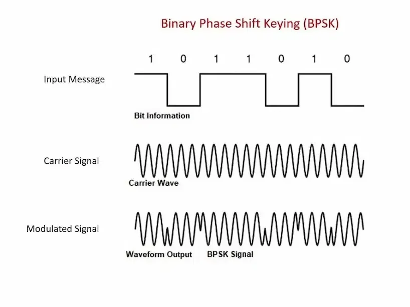
This type of modulation is simple to implement and has a big advantage: a big error tolerance. Let’s look at this last point in more detail. When the modulated signal is transmitted and travels through space, it will suffer from different types of disturbances that will modify its characteristics. An example of a disturbance can be interference (other signals on the same frequency). An important characteristic of the modulation technique used is how much it tolerates these disturbances. That is, how much modification a symbol can undergo without being confused by a different symbol at the receiver (and, consequently, the data being incorrectly interpreted).
As an example in the case of BPSK, if we think that both symbols are in counter phase (separated by an angle of 180°) then the modification would have to be more than 90° of phase offset to have a de-modulation error. This is usually best visualised with a diagram called a constellation. The picture below shows the constellation of a BPSK modulation.
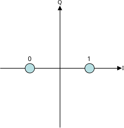
Each symbol is represented by a light blue circle. In a constellation, the distance to the centre represents the amplitude of the wave, and its angle to the I-axis represents the phase. With BPSK we are not modifying the amplitude, so both symbols are at the same distance from the centre. As BPSK modifies the phase, we see one symbol with phase 0º (representing the binary 1) and another with phase 180º (representing the binary 0).
Note: To understand better what a constellation is in this context, I recommend reading this article from the PySDR project.
Going back to the error probability, let’s put a mask on the constellation to understand how the receiver would make a decision about which symbol is received:
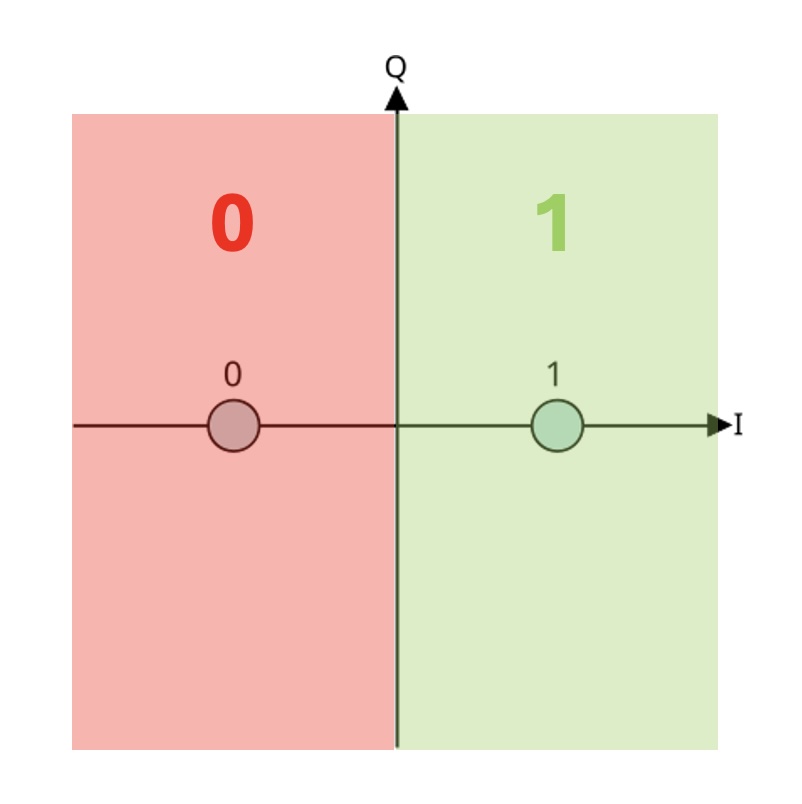
We will come back to this figure later, because we need to compare it with another modulation to understand its importance. With BPSK, each symbol carries one bit of information. The transmission speed is low for this same reason. If we want to send more information, we can think of having four different symbols, each representing two bits of information. This modulation is called Quadrature PSK (QPSK). Let’s look at the constellation of this type of modulation.
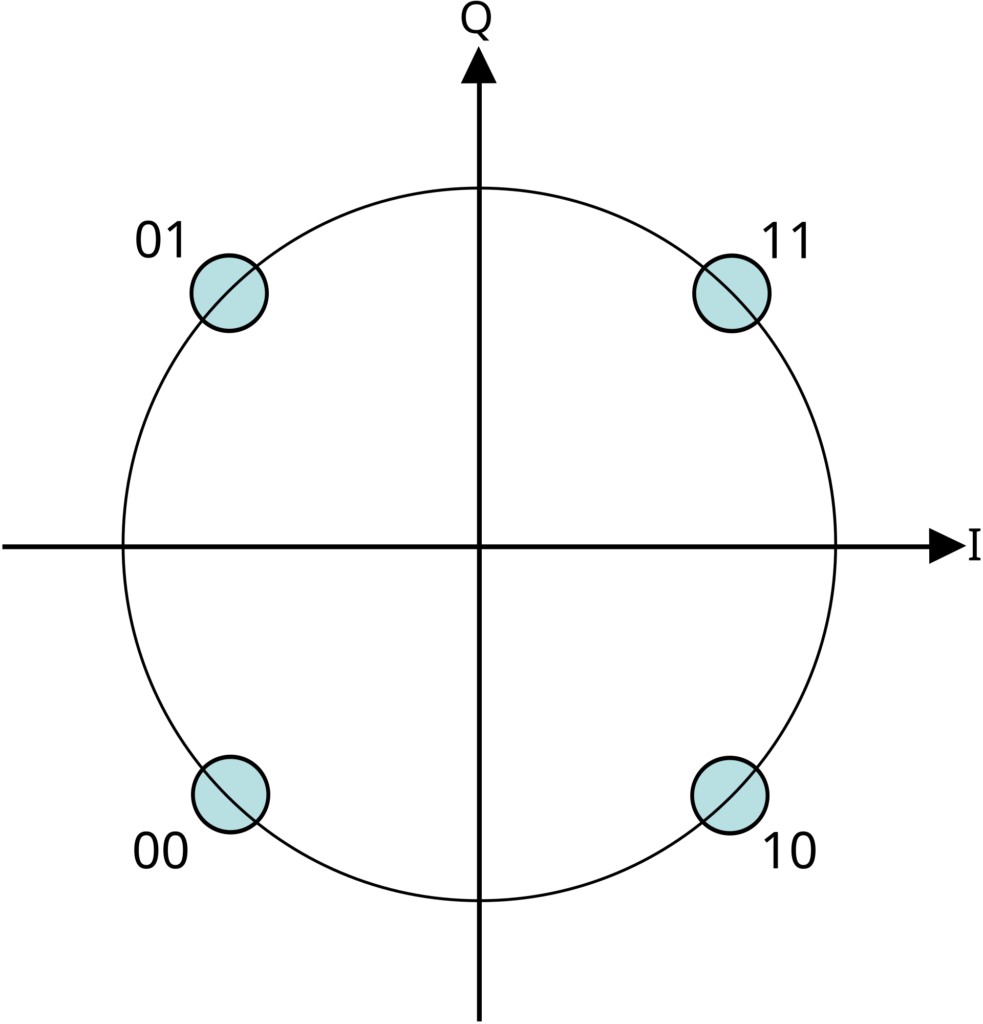
We now have a higher transmission speed! And so we could increase the number of symbols and transmit more information per symbol. The picture below shows several constellations: BPSK, QPSK and 8-PSK (3 bits per symbol). This serves to illustrate what happens when we increase the number of symbols: the symbols get closer together (there is less phase difference between them).
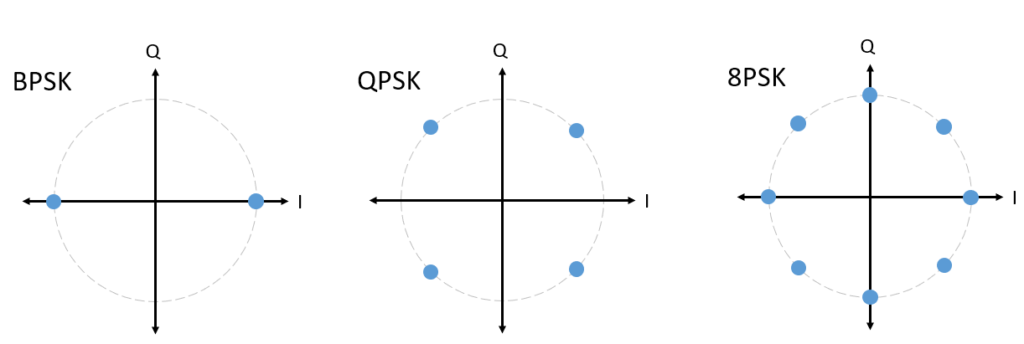
Closer symbols mean that the probability of error if the signal is affected in transmission is higher. Comparing the picture below (representing the decision of a QPSK receiver) with Figure 12, the following conclusion can be drawn: higher speed implies less fault tolerance.
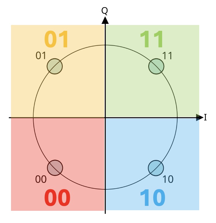
If we want to further increase the speed, we have to guarantee error-free transmission. For this it is important to have a very good signal strength in reception, or we must switch to an different modulation technique.
Amplitude Shift Keying – ASK
Another property of the carrier wave that we can modify is its amplitude. Amplitude Shift Keying (ASK) does exactly this. Each symbol is represented by a different amplitude on the carrier wave. Like PSK, the most basic form has two symbols (binary 0 and 1). As the number of symbols increases, amplitude values closer to each other are used, thus increasing the probability of error at the receiver.
The figure below serves to illustrate the result of a 2-ASK modulation.
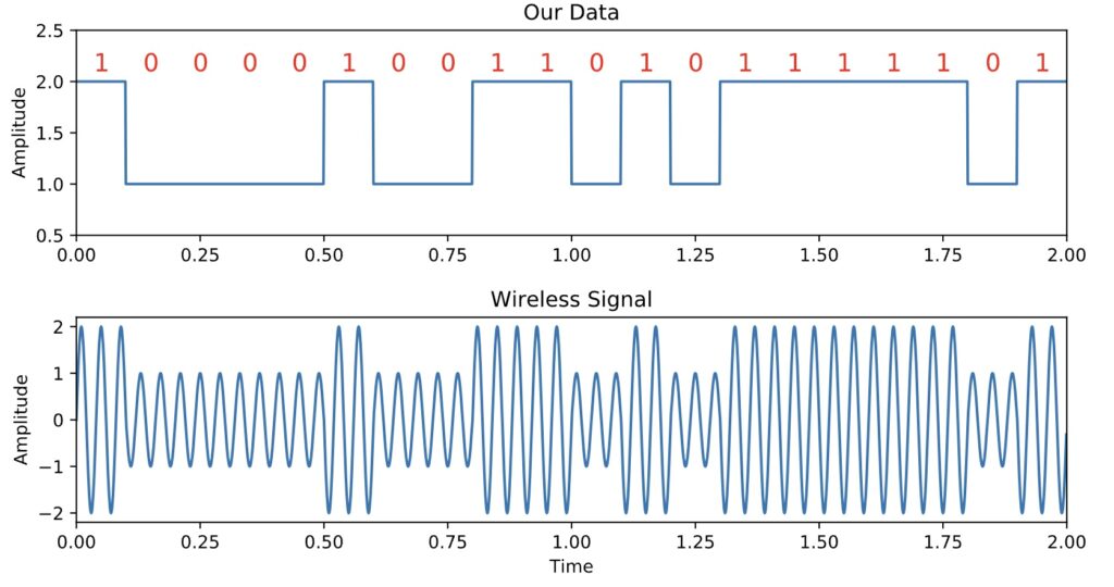
ASK symbols can also be displayed as a constellation. In ASK the phase remains constant and the amplitude changes. Therefore, the symbols move away from the centre of the constellation. The picture below shows constellations for various orders of ASK.
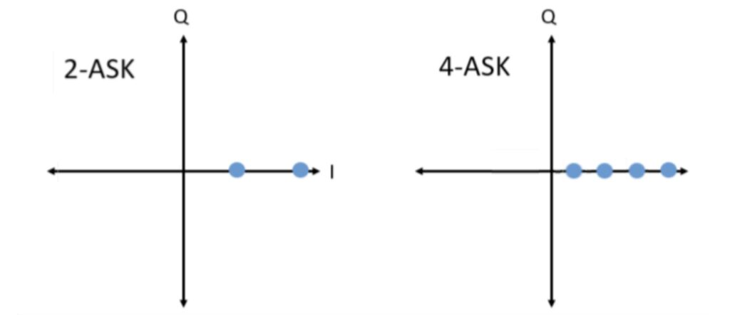
ASK is more sensitive to noise than PSK, but has the advantage that it needs less bandwidth to operate. This point was not mentioned before, because it is complex to explain. But indeed, to modulate a carrier wave oscillating at a certain frequency, a certain range of frequencies around this central frequency is needed. A common point for all modulation techniques is that the higher the transmission rate the higher the bandwidth needed. And if we compare ASK and PSK at the same transmission rate, ASK will need less bandwidth.
The choice of which modulation technique to use will then depend on what is the most critical point in the communication.
Quadrature Amplitude Modulation – QAM
Quadrature Amplitude Modulation (QAM) is a modulation technique that modifies not one, but two properties of the carrier wave. Each symbol uses a different phase and amplitude. With this modulation technique, a large set of symbols can be arranged efficiently. Again, there are different orders depending on the number of symbols available. Examples are 16-QAM, 64-QAM and 256-QAM.
If we recall the constellation analysis of the previous techniques, it will be easy to understand the QAM constellation. The picture below shows the constellation for 16-QAM.
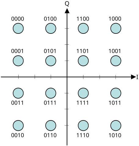
The use of very high level QAM (1024-QAM for example) is usual in Wi-Fi to achieve higher speeds. But such high modulation levels are very sensitive to errors. They need a much higher signal strength than the noise for this reason. This point will be discussed in more detail in the next entry in this series, when we look at Wi-Fi in detail.
Wireless protocols
Almost everything in the world of telecommunications is governed by protocols. And wireless communications is not exempt from this. What is the use of wireless protocols? They define the rules for wireless communication between two devices. These rules allow us to ensure that no matter the manufacturers of the components involved in the communication, the information will be able to reach its destination successfully.
The next entries in this series will be dedicated to one of these protocols: Wi-Fi. Wi-Fi is based on the IEEE 802.11 family of protocols and defines some of the following:
- Frequencies of operation – Wi-Fi operates in several frequency bands (2.4 GHz, 5 GHz and 6 GHz).
- Modulation techniques used – ranging from BPSK to 4096-QAM.
- How to select the best modulation to use.
- How the transmitted information is controlled, how to detect and correct errors.
- How multiple devices that want to transmit or must receive information at the same time coexist.
- How to secure the communication channel.
All these functions and rules defined in the different Wi-Fi standards will be part of the content of the following posts in this series. But to conclude this post, let’s look at other well-known wireless protocols. All of them are governed by the basic concepts we have discussed so far:
- Bluetooth & Bluetooth Low Energy
- Cellular technology – LTE (4G), 5G, etc.
- LoRaWAN
- Zigbee
- And a lot more…

This post is already long enough. In the next one, we are going to analyse in detail how a Wi-Fi network works. While I’m writing it, feel free to let me know if you have any suggestions or questions. See you next time!
